1-EventFlag explanation
How does the scmRTOS sample work and what is happening there?
Illustrated explanation.
The explanation is based on avr-gcc (WinAVR) port for AVR microcontrollers but can be useful for understanding of each scmRTOS port.
Sample 1-EventFlag was slightly changed to demonstrate actions occuring in the system. Pin state change commands where added into context switcher (file OS_Target_asm.S), processes’ functions Exec() and into functions IdleProcessUserHook(), SystemTimerUserHook(), TIMER1_COMPA_vect() (file main.cpp).
User-controlled pins are assigned in file main.cpp:
55 56 57 58 59 60 61 62 63 64 65 | //------------------------------------------------------------------- // "Hello, scope!" pins (pin numbers for ATmega168 in DIP28 package) // Define pins in form PORT_LETTER,PORT_PIN,ACTIVE_LEVEL // (Ascold Volkov - type "pin_macro.h" notation) #define TIMER1_ISR_PIN C,4,H // pin 27 #define T1PROC1_PIN B,0,H // pin 14 #define PROC1_PIN B,1,H // pin 15 #define PROC2_PIN B,2,H // pin 16 #define PROC3_PIN B,3,H // pin 17 #define TIMERHOOK_PIN B,4,H // pin 18 #define IDLEHOOK_PIN B,5,H // pin 19 |
A context-switcher-controlled pin is assigned in makefile:
11 12 13 | # Define contect switch "Hello, scope!" pin in form PORT_LETTER,PORT_PIN # C,5 for pin5 of PORTC SWITCH_PIN=C,5 |
Microcontroller pins are connected to a logic analyser. The microcontroller is clocked by internal 8 MHz RC-oscillator, one system timer tick is about 2 miliseconds.
scmRTOS and its samples source codes can vary in a repository. Moreover the context switcher for real pojects can’t contain pin control commands. So these commands have been removed from the code in the repository.
You can download the archive 1-EventFlag-explanation.zip with modified scmRTOS and the 1-EventFlag sample which conform to this explanation.
The sample is prepared for avr-gcc (WinAVR) compiler and for one of ATmega48/ATmega88/ATmega168/ATmega328 microcontroller. You may need to change the sample source in accordance with timers and pins which are used in another controller.
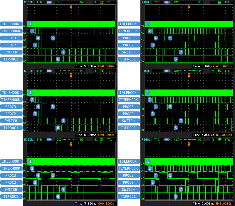
Logic analyser inputs assignment
| D5 | IDLEHOOK |
Signal is toggled in
IdleProcessUserHook(). |
|---|---|---|
| D4 | TIMERHOOK |
Signal is toggled in
SystemTimerUserHook() |
| D3 | PROC3 |
Signal is risen and fallen in
TProc3::Exec(). |
| D2 | PROC2 |
Signal is risen and fallen in
TProc3::Exec(). |
| D1 | SWITCH |
Signal is risen by the first context switcher command and is fallen before exit (just before
reti). |
| D0 | T1PROC1 |
Signal is risen in
TIMER1_COMPA_vect() ISR and is fallen in TProc1::Exec(), which waits for timer1 event. |
Proc2 and Proc3 interaction — bird’s-eye view
Sample compilation options:
main.cpp
86 | #define PROC2_LONG_PULSE 1 |
Proc2 generates a pulse with width is one system timer tick. Another compilation paramenrs are not significant for this scale.

-
Signal IDLEHOOK is a square wave with period of a few microseconds. It’s displayed like a solid strip.
-
Function
OS::SystemTimerUserHook()inverts TIMERHOOK state, so there is a square wave with period of two system timer ticks (about 4 ms) on corresponding line. Edges on lines PROC2 and PROC3 are synchronous with state changes on line TIMERHOOK. -
There are two sleepeing function calls in
TProc2::Exec().Sleep(1)specifies pulses’ length on line PROC2 whileSleep(9)specifies the time between pulses. So Proc2 is a generator with 20 ms period and 2 ms pulse length. -
Before Proc2 falls PROC2 line and goes to sleep for ten ticks it wakes up Proc3 by
ef.Signal();call. AfterTProc3::Exec()gets control it rises PROC3 line and goes to sleep again bySleep()call. Sleeping time is selected by bit 9 of a system tick counter which value is returned byOS::GetTickCount();. During 512 ticks (about 1 second) the sleeping time is two timer ticks and during another second the time is three ticks. -
Waking up by system timer Proc3 falls PROC3 line and goes to sleep by
ef.Wait();call until Proc2 activatesefevent. Proc3 is a single-shot pulse generator started by falling edge on PROC2 line. -
Pulses on line T1PROC1 are produced in
TIMER1_COMPA_vect()interrupt handler. The interrupt is activated with a period not multiple of system tick so the pulses are not synchronized with the system timer. Timer 1 and Proc1 interwork is described below. -
You can see processes switching markers on line SWITCH. A part of them corresponds to edges on lines PROC2 and PROC3, another one — on line T1PROC1.
Proc2 to Proc3 switching — detailed view
The sample and OS compilation options (a common part for both variants):
scmRTOS_CONFIG.h
124 | #define scmRTOS_CONTEXT_SWITCH_SCHEME 1 |
Context switching is made by the lowest priority level interrupt which is requested by software. Switching scheduled in interrupt processing starts after ISR exit.
main.cpp
86 | #define PROC2_LONG_PULSE 0 |
For detailed view one system timer tick delay is removed from pulse generation code in Proc2. The pulse length is determined by function ef.Signal() execution time and, in variant 2, by process switching time and Proc3 activity time.
Variant 1
Extra compilation options:
main.cpp
85 | #define PROC2_HIGHER_THAN_PROC3 1 |
Proc2 priority is higher than Proc3 one.

-
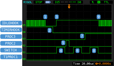
IDLEHOOK toggling in function
IdleProcessUserHook()is stopped when control is transferred to the system timer interrupt routine. -
After system part of ISR is completed
SystemTimerUserHook()is called. In this function TIMERHOOK line state is toggled. -
Control flow leaves the system timer ISR and enters the context switcher interrupt.
One command from interrupted process code can be executed between two interrupts. In this diagram it is a IDLEHOOK line toggling command. -
Context switcher transfers control to Proc2 at
Sleep(9)return point. The first switcher command rises SWITCH line and last-but-one command falls the line. The pulse length shows the time necessary for context switching without the time for scheduling. -
TProc2::Exec()rises PROC2 line, callsef.Signal()and then falls PROC2 line. We can determineSignal()function execution time by the pulse length. ThenTProc2::Exec()callsSleep(10)and goes to sleep again. scmRTOS scheduler searches for ready process. There isTProc3which has already recieved the signal. -
The next process switching takes place (the second pulse on SWITCH line).
TProc3::Exec()gets control. -
Proc3 rises PROC3 line, reads system timer value and goes to sleep for appropriate time. This is described above in section “Proc2 and Proc3 interaction — bird’s-eye view”.
-
Next scheduling. There is no ready user’s process and control flow is transferred to
IdleProcess(the third pulse on SWITCH line). -
TIdleProcess::Exec()gets control and IDLEHOOK toggling is restored. The pause while the signal is not toggling shows the whole time for hardware interrupt service routine (ISR), process scheduling, context switching, processes’ activity and switching back toIdleProcess.
Processes switching path is IdleProcess → Proc2 → Proc3 → IdleProcess. Three context switches total.
Variant 2
Extra compilation options:
main.cpp
85 | #define PROC2_HIGHER_THAN_PROC3 0 |
Proc2 priority is lower than Proc3 one. Events are similar to “Variant 1” but there are some differencies after ef.Signal() call in TProc2::Exec().
Diagramm changes in this way:

-
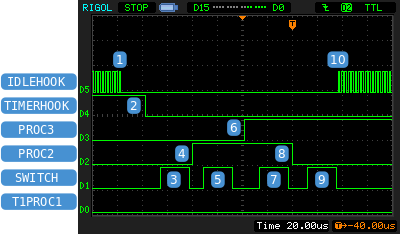
IDLEHOOK toggling in function
IdleProcessUserHook()is stopped when control is transferred to the system timer interrupt routine. -
After system part of ISR is completed
SystemTimerUserHook()is called. In this function TIMERHOOK line state is toggled. -
The first cointext switching interrupt transfers control flow to Proc2 at
Sleep(9)return point. -
TProc2::Exec()rises PROC2 line and callsef.Signal(). Unlike variant 1ef.Signal()returns control not immediately. In this variant Proc3 priority is higher than Proc2 one so scheduling atef.Signal()end activates switching to Proc3. -
Process switching (the second pulse on SWITCH line).
TProc3::Exec()gets control. -
Proc3 rises PROC3 line, reads system timer value and goes to sleep.
-
There is one more active process — Proc2. Context is swithed back to
TProc2::Exec()(the third pulse on SWITCH line). -
And just now control flow “returns” to
TProc2::Exec()fromef.Signal(). Finally PROC2 line falls. On this diagramm the pulse on PROC2 line is much longer than one for previous variant because it includes Proc3 working time and two process switchings.
TProc2::Exec()callsSleep(9)again, scmRTOS searches for a ready process. Proc3 have already done its work so there is the only ready process —IdleProcess. -
Last context switching transfers control to
TIdleProcess::Exec(). -
TIdleProcess::Exec()gets control and IDLEHOOK toggling is restored.
For such priority realtion processes switching path is
IdleProcess → Proc2 → Proc3→ Proc2 → IdleProcess
Four context switches total.
On the one hand IdleProcess was interrupted for longer time.
On the other hand Proc3 has got control a bit earlier.
What variant is better depends on system requirements. This sample just shows that a system reaction depends on right priority assignment.
Signal transferring from timer 1 interrupt to process 1
The difference from previous sections is that OS::TEventFlag Timer1_Ovf; transfers the signal from an interrupt routine to a process but not from one process to another one.

-
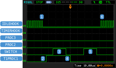
IDLEHOOK toggling in function
IdleProcessUserHook()is stopped when control is transferred to the system timer interrupt routine. -
TIMER1_COMPA_vect()rises T1PROC1 line and sends a signal to Proc1 byTimer1_Ovf.SignalISR();call. This signal asks process switching so that the scheduler activates context swithcing interrupt request. -
Context switching interrupt processing starts after
TIMER1_COMPA_vect()exit.TProc1::Exec()gets control. -
Proc1 falls T1PROC1 line and goes to sleep again by
Timer1_Ovf.Wait();call untilTIMER1_COMPA_vect()activatesTimer1_Ovfevent.T1PROC1line pulse length shows a minimal delay from a hardware event to a high priority precess gets control. -
There is no a ready process and the second context switching interrupt returns control to
IdleProcess. -
TIdleProcess::Exec()gets control and IDLEHOOK toggling is restored.
© 2008-2010, Oleksandr Redchuk aka ReAl
 українська
 english
Вы предлагаете все-таки установи scmRTOS_CONTEXT_SWITCH_SCHEME равным 1 и вернуть кодинициализации прерывания от компаратора?
Почему «всё таки» (это еще не «несмотря ни на что», но близко)? В крупном масштабе диаграммы уже немного зависят от способа организации переключателя контекста, поэтому я уточнил. Чаще использовал прерывание от SPM, а не от компаратора, так как бутлоадер не использовал, а компаратор или, по крайней мере, выводы микроконтроллера — нужны.
Заранее извиняюсь если не коректный вопрос. И не в тот раздел)Сколько человек здесь делятся опытом?Спасибо!
В последнее время — пол человека ± четверть.
Читаю тут комментарии через RSS. 🙂 Но сам сейчас чего-либо на AVR не конструирую, хотя остались всякие идеи и “замороженные проекты”. 🙂 Из последнего на тему “embedded” у меня были небольшие Python-скрипты для Raspberry Pi – эксперименты с http-запросами и подключением через GPIO.
Через блокнот WinAvr все оказалось просто. Нужно выбрать в главном меню блокнота File/New/Project и создать проект с любым именем в папке с примером. Затем подключить к проекту все фалы примера, в том числе и файл без расширения makefile. Далее открыть в блокноте makefile и выполнить команду из гланого меню блокнота Tools/[WinAvr]Make All. В результате должна появиться папка exe где и будет требуемый .hex файл для прошивки в контроллер.
По ходу песни возникли некоторые вопросы.
1.В чем всетаки разница между контекстом и процессом. Разве это не одно и то же?
2.И всетаки чем конкретно в данном примере переключаются контексты (речь идет о программном прерывании самого низого уровня). Где можно посмотреть как организовано это прерывание в тексте примера.
3. Получается что программа обработки прерывания по Timer1 это тоже процесс (он может быть короткий, а может быть длинный) или нет? Или программа обработки прерывания только передает управление нужному процессу? Так зачем передавать? Только трата времени. Разве не так?
Да оно и не должно было быть сложно 🙂
Просто я для всего под Windows ипользовал MED и не слазил бы с него, если бы не желание работать в кроссплатформенном редакторе. Сейчас болтаюсь между NetBeans и Code::Blocks, но, похоже, надо плыть в сторону Eclipse…
1. Процесс обслуживается операционной системой. У процесса есть код (в случае AVR — во флеше), есть, скажем так, «описатель» (переменная TProc). И есть все те внутренности ядра микроконтроллера, которые описывают текущее состояние микроконтроллера при выполнении данного процесса — текущий указатель команд, указатель стека, содержимое регистров общего назначения и статусный регистр SREG. Вот эти вещи и называются контекстом, их надо сохранять и восстанавлиать при переключении процессов. Для AVR/GCC порта указатель стека сохраняется в «описателе» процесса, а весь остальной контекст — на стеке процесса.
2. Контексты переключаются либо прямым программным вызовом
os_context_switcher(), либо прерываниемCONTEXT_SWITCH_ISR_VECTOR:в зависимости от настроек ОС для данного проекта. Код обеих переключателей находится в файле scmRTOS/AVR/OS_Target_asm.S, нужный вариант выбирается директивами условной компиляции.Обработчик прерывания — не процесс, а, в некотором смысле, «продолжение аппаратуры». По крайней мере, он не подчинён ОС, она не передаёт ему управление. А обработчик меняет состояние объектов ОС, в результате чего она может переключить процессы.
3. Вопрос о том, что делать в обработчике, а что поднимать на уровень процесса, решается для каждого проекта. В обработчике должен сидеть «драйвер» периферийного объекта или, по крайней мере, вся его низкоуровневая часть.
На мой взгляд, всю обработку состояний интерфейса стоит производить в обработчике, отдавая наверх событие «транзакция завершена». Процесс проснётся и обработает только результат успешно/неуспешно, подумает, что делать дальше.
Я бы сказал так — если действия по времени занимают менше пары-тройки переключений с процесса на процесс (одно переключение — две-две с половиной сотни тактов), то нет никакого смысла их поднимать на уровень процесса. Если больше десяти, то врядли стоит занимать столько времени, блокируя тем самым выполнение высокоприоритетных задач, а затраты на переключение уже не так и велики на фоне работы. Между этими границами переходная зона. Чем менее приоритетным процессам нужен результат работы прерываний, тем меньше времени в этом прерывании нужно проводить.
“Чем менее приоритетным процессам нужен результат работы прерываний, тем меньше времени в этом прерывании нужно проводить” – неплохо сказано.
Если не сложно, можно прокомментировать этот код из обработчика пр.таймера Т1
ENABLE_NESTED_INTERRUPTS();
Timer1_Ovf.SignalISR();
Объект
ISRW— ISR Wrapper. Его создание просто заставляет отработать его конструктор на входе в обработчик и его деструкутор на выходе, а в них помещены те действия, которые нужны для интеграции прерывания в scmRTOS. Т.е. работа со счётчиком вложенных прерываний и запуск перепланировщика при выходе из прерываний в основной код.Далее разрешаются вложенные прерывания. Тут это не нужно, прерывание короткое, но надо же как-то продемонстрировать и проверять работоспособность.
После чего взводится событие таймера — помечаются как готовые все процессы, которые его ожидают.
В приведенном примере кода не хватает для комментирования очень важной строки 🙂
По ней заканчивается область определения переменной
ISRWи отрабатывает деструктор объекта. В деструкторе вызывается планировщик ОС, просматривающий таблицу процессов и, в данном примере, сразу передающий управление на самый приоритетный процессTProc1.Хороший пример. Очень хотелось-бы его запустить в реальном железе. Но проблема в том, что я, как и многие другие не знакомые с WinAvr, понятия не имеют как пример запустить на компиляцию в WinAVR. Информации по этому поводу в сети нет или она никуда не годится. Вроде все должно быть не сложно. Но кроме простого открытия файлов в WinAvr дело дальше не пошло. Если не сложно добавьте пожалуйста к статье последовательность как добавить и откомпилировать пример в WinAvr с получением .hex.
При установке WinAVR он прописывает в PATH два пути — к компилятору и к утилитам (из которых интересуют make и sh). Из командной строки всё становится доступным без лишних телодвжений.
Самый простой, по крайней мере для меня :-), путь сборки примера — зайти FAR-ом в каталог 1-EventFlag и набрать команду
make.Идущим в поставке WinAVR редактором Programmers Notepad я никогда не пользовался, поэтому не могу сказать, как собирать пример из него.